


 当前位置:
当前位置:Reference Design for a Class-D
[11-20 17:32:34] 来源:http://www.88dzw.com 模拟电子技术 阅读:8343次
文章摘要:Detailed Design DescriptionThe reference design consists of a single, carefully tuned box enclosure containing all of the electronics and speaker hardware. Only an external power supply and a signal source are required to complete the system.The design features two 2in loudspeaker drivers for the le
Reference Design for a Class-D,标签:模拟电子技术基础,模拟电子电路,http://www.88dzw.comDetailed Design Description
The reference design consists of a single, carefully tuned box enclosure containing all of the electronics and speaker hardware. Only an external power supply and a signal source are required to complete the system.
The design features two 2in loudspeaker drivers for the left and right channels, and a 5in loudspeaker for the subwoofer. A single MAX9736B is used in stereo mode for the left/right channels and a MAX9736A is used in mono mode for the subwoofer channel. The detailed description here is divided into two sections: electronic circuit description and speakers/physical enclosure description.
Electronic Circuit Description
The electronics of the reference design comprise two sections, the left/right and subwoofer. Each section has three stages: input, EQ, and power. See Figure 1.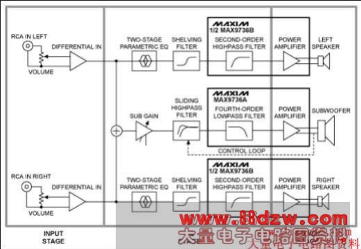
Figure 1. Electrical circuit block diagram features the MAX9736 Class D audio amplifier. The design has an input, EQ, and power stage.
Input Stage
The input stage is common to both the left/right and subwoofer sections. A stereo, log-taper potentiometer is used as a volume control to adjust the signal level to the preamplifier. To avoid ground loops, the input is sensed differentially and the RCA input connectors are not directly connected to the system ground. A 100Ω resistor is used to reduce the common-mode voltage; U3-A and U3-D (see schematics below) perform differential-to-single-ended conversion with a gain of 2. The outputs of the input stage are referred to VREF, the reference voltage of power amplifier U2 which is buffered using U5-D.
EQ Stage
After the input stage, the left and right signals are passed to a two-stage parametric EQ built around U3-B (for left) and U3-C (for right). Each parametric EQ uses an op-amp gyrator to simulate an inductor in an LC-series resonant circuit. The series circuit has two access points for either attenuation or boost, and the access points are realized by two different capacitors. C105 and C106, for example, are the boost and attenuation points for the first parametric EQ band for the left channel. If only C106 is used (and C105 is not stuffed), the resonant circuit forms a voltage-divider in combination with the series resistor R105 (10kΩ), and the resonant frequency is attenuated. Conversely, if only C105 is used, the feedback is reduced, resulting in a boost at the resonant frequency. If neither of the capacitors is used, then the band is disabled.
The resonant frequency, f0, can be calculated using the equation:
f0 = 1/(2 × π × √(L0 × C0))
Where:
L0 = R108 × C107 × R107
C0 = C105
And the Q is:
Q0 = √(L0/(C0 × R0²))
A third EQ band is added that realizes a shelving filter and only needs an RC: one capacitor (C113 for boost; C114 for attenuation) and one resistor (R111).
《Reference Design for a Class-D》相关文章
- › Reference Voltage for Multiple
- › Understanding Voltage-Referenc
- › Reference Design for a Class-D
- › 确保打印头电源动态输出电压的参考设计,Reference D
- 在百度中搜索相关文章:Reference Design for a Class-D
- 在谷歌中搜索相关文章:Reference Design for a Class-D
- 在soso中搜索相关文章:Reference Design for a Class-D
- 在搜狗中搜索相关文章:Reference Design for a Class-D