


 当前位置:
当前位置:Measuring Temperature with the
[11-20 17:33:01] 来源:http://www.88dzw.com 模拟电子技术 阅读:8176次
文章摘要:Using Equation 2 above and substituting the measured values:Solving the equation for the temperature yields: TMEAS = 300.19KConverting the result from Kelvin to Celsius yields: °C = 300.19 - 273.15 = 27.04°CThis is the measured value at room temperature. A correction for gain and offset has not been
Measuring Temperature with the,标签:模拟电子技术基础,模拟电子电路,http://www.88dzw.comUsing Equation 2 above and substituting the measured values:
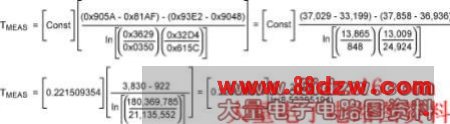
Solving the equation for the temperature yields: TMEAS = 300.19K
Converting the result from Kelvin to Celsius yields: °C = 300.19 - 273.15 = 27.04°C
This is the measured value at room temperature. A correction for gain and offset has not been applied. The gain and offset correction is detailed below.
External Four-Current Method
The external four-current method is the same as the internal four-current method, except that the internal current-source multiplexer must be changed to direct the current source out AIN1 or AIN2. The ADC input multiplexer must also be changed to use AIN1 and AIN2 as the ADC inputs.
The external components are connected as shown in Figure 1 above. The external transistor chosen for this application is a low-cost surface-mount 2N3904 from On Semiconductor, part number MMBT2N3904LT1. Other transistors or diodes can also be selected. The resistor chosen is a low-cost surface-mount 4.02K 1% size 0805 1/8 watt from Panasonic®, part number ERJ-6ENF4021V. This value resistor was chosen to match the internal resistor, which is typically 4KΩ.
Procedure Using the External Transistor
The procedure for measuring the voltages across the external transistor and external resistor is similar to the internal four-current method, except that the current source must be selected to drive AIN1 or AIN2 and different inputs must be selected to read the external VBE and VR.
Step 1. Enable the Reference and ADC
Enable the internal 1.251V reference and the reference buffer with a gain of 1.0 by setting REFV[1:0] bits to 0x01 in the REF_SDC register.
Enable the ADC by setting the ADCE bit in the ADC register. The internal reference and ADC are enabled. Note: The ADC is set with the default parameters of unipolar, normal polarity, single conversion, internal reference, unity gain, 10 samples per second, and normal conversion.
Step 2. Calibrate the ADC
Set the ADC conversion mode to Self Offset and Gain Calibration by setting the Mode[2:0] bits to 0x07 in the ADC register. Start an ADC conversion by setting STRT bit in the ADC register. The ADC is now calibrated. The Mode[2:0] bits in the ADC register are automatically cleared. This returns the ADC to normal operation.
Step 3. Set the Current Source for Internal AIN1
Set the current source for internal temperature sensor by setting the IMUX[1:0] bits to 0x10 in the TEMP_CTRL register.
Step 4. Set the Current Source for I1 (4µA)
Set the current source for I1 by setting the IVAL[1:0] bits to 0x00 in the TEMP_CTRL register.
Step 5. Set the ADC Input for AIN1 to AIN2
Set the ADC positive input multiplexer for AIN1 by setting MUXP[3:0] to 0x00 in the MUX register. Set the ADC negative multiplexer for AIN2 by setting MUXN[3:0] to 0x07 the MUX register.
Step 6. Measure VBE1 Using the ADC
The VBE1 voltage is measured from the AIN1 to the AIN2 inputs to the ADC. The ADC is configured and only needs to convert to get the resulting V
上一页 [1] [2] [3] [4] [5] [6] [7] [8] 下一页
《Measuring Temperature with the》相关文章
- › Measuring Temperature with the
- 在百度中搜索相关文章:Measuring Temperature with the
- 在谷歌中搜索相关文章:Measuring Temperature with the
- 在soso中搜索相关文章:Measuring Temperature with the
- 在搜狗中搜索相关文章:Measuring Temperature with the