


 当前位置:
当前位置:DS1670便携式系统控制器-DS1670 Portable
[09-13 17:03:21] 来源:http://www.88dzw.com 控制技术 阅读:8204次
文章摘要:Abstract: This application note describes how to use the DS1670 Portable System Controller, a 3-wire serial interface real-time clock (RTC). The DS1670 supplies features that are targeted at portable (hand held) systems. FeaturesThere is an increasing trend in the industry today towards portable bat
DS1670便携式系统控制器-DS1670 Portable,标签:计算机控制技术,工厂电气控制技术,http://www.88dzw.comAbstract: This application note describes how to use the DS1670 Portable System Controller, a 3-wire serial interface real-time clock (RTC). The DS1670 supplies features that are targeted at portable (hand held) systems.
Features
There is an increasing trend in the industry today towards portable battery-operated products. These products typically require extremely small form factors and low power. The DS1670 Portable System Controller is designed to help the portable system designer in meeting these two requirements by integrating key functions typically needed in these systems while consuming very little power.Key functions frequently required in portable products include a real time clock; nonvolatile RAM control to ensure that data is not lost in the event of a power-down or battery-fail; microprocessor monitoring to ensure that the microprocessor does not "run out of control"; and analog-to-digital converters for interfacing with external environmental sensors, battery monitoring, etc. The DS1670 Portable System Controller replaces as many as four separate integrated circuits by incorporating all of these functions in a single device. The DS1670 provides a very accurate real time clock, nonvolatile SRAM controller, microprocessor monitor, and 3-channel 8-bit analog-to-digital converter. Communication with the device is established through a simple 3-wire interface.
Using the DS1670
The DS1670 can be directly interfaced with any microprocessor or microcontroller through a 3-wire serial interface. The serial interface gives the microprocessor access to the DS1670 registers, which consist of the Real Time Clock Registers, Control Register, Status Register, Watchdog Register, and ADC (Analog-to-Digital Converter) Register. Figures 1 and 2 illustrate a block diagram and address map of the DS1670, respectively. The following paragraphs briefly describe the operation of the various components of the DS1670 as well as the functions of the various control and status registers. For more detailed information, please consult the DS1670 data sheet.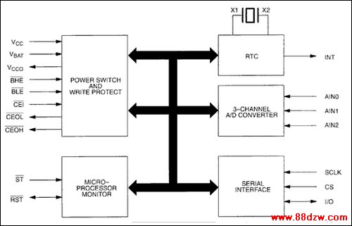
Figure 1. DS1670 block diagram.
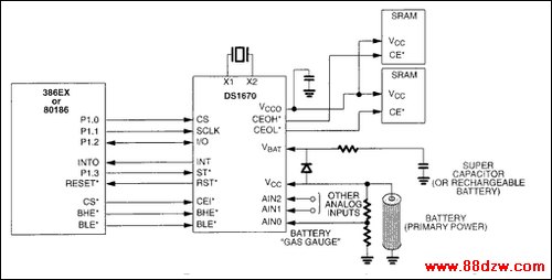
Figure 2. Typical application.
Real Time Clock
The Real Time Clock (RTC) provides seconds, minutes, hours, day, date, month, and year information with leap year compensation. The RTC has a back-up power supply input (VBAT) that enables it to continue to keep time even when the primary supply connected to VCC is removed. The RTC also provides an alarm interrupt which is functional both when the DS1670 is powered by the system power supply or when in battery back-up operation. Functionality while in battery back-up operation allows the alarm to "wake up" a system that is powered down.Nonvolatile SRAM Control
The nonvolatile SRAM controller of the DS1670 provides two important functions. First, it ensures a constant uninterrupted power supply to the system SRAMs. This is provided by the VCC Output pin (VCCO). VCCO is internally connected to VCC when VCC is within nominal limits. However, when VCC is below nominal limits, VCCO is connected to the power source connected to VBAT (typically a lithium battery, rechargeable battery, or super capacitor). The second important feature of the nonvolatile controller is that it gates the chip enable signals to the SRAMs. This ensures that the microprocessor can access the SRAMs only when the primary power supply is within nominal limits, thus eliminating the corruption of data during power transients. It should also be noted that the DS1670 provides nonvolatile control for two separate SRAMs. The two inputs from the microprocessor are Byte High Enable (active-low BHE) and Byte Low Enable (active-low BLE). These inputs correspond to the two output Chip Enable Output High (active-low CEOH) and Chip Enable Output Low (active-low CEOL).
Tag:控制技术,计算机控制技术,工厂电气控制技术,控制技术
《DS1670便携式系统控制器-DS1670 Portable》相关文章
- › 驱动器和通信电路引脚及主要特性DS1692/3692 三态差动线驱动器
- › 驱动器和通信电路引脚及主要特性DS1691A/3691 RS-422/423驱动器
- › 驱动器和通信电路引脚及主要特性DS1687/3687 负电压延迟驱动器
- › 驱动器和通信电路引脚及主要特性DS1649/3649六进制三态TTL-MOS驱动...
- › 驱动器和通信电路引脚及主要特性DS1648/3648三态TTL-MOS多路转换器...
- › 驱动器和通信电路引脚及主要特性DS1631/2/3/4、DS3631/2/3/4 驱动...
- 在百度中搜索相关文章:DS1670便携式系统控制器-DS1670 Portable
- 在谷歌中搜索相关文章:DS1670便携式系统控制器-DS1670 Portable
- 在soso中搜索相关文章:DS1670便携式系统控制器-DS1670 Portable
- 在搜狗中搜索相关文章:DS1670便携式系统控制器-DS1670 Portable
分类导航
最新更新