


 当前位置:
当前位置:MAX-IDE Simulator User's G
[09-13 17:04:09] 来源:http://www.88dzw.com 控制技术 阅读:8333次
文章摘要:Step 2: Before proceeding with the project menu, you need to add files to this project. From the main menu create a new source file by choosing File→New File from the menu. This will open a new editor window with the title "Untitled 1." Enter the assembly code shown in Table 1 below. Alter
MAX-IDE Simulator User's G,标签:计算机控制技术,工厂电气控制技术,http://www.88dzw.comStep 2: Before proceeding with the project menu, you need to add files to this project. From the main menu create a new source file by choosing File→New File from the menu. This will open a new editor window with the title "Untitled 1." Enter the assembly code shown in Table 1 below. Alternatively, you can download the assembly code and add this file to the project, as explained in Step 4 below. Figure 2 shows the MAX-IDE with the project manager and editor windows open.

Figure 2. Use the project manager and editor windows to create a new file.
Step 3: Before adding this new file to the project, you need to save this file. Choose File→Save Untitled1 which opens the Save As dialog box. Create a new folder, MAXIDE, and save the file to the MAXIDE folder as hex_to_asc.asm.
Step 4: To add the source file that we just created to the project, choose Project→Add Files. This will open up the Open dialog box. Browse to the folder that you created in the previous step, and select hex_to_asc.asm file. You can also perform this operation by right clicking in the project window, and choosing Add Files from the pop-up window.
Note: Even if you created the source file in the IDE, it will not be part of the project until you add it to the project file
Step 5: To save the progress so far, choose Project→Save from the menu, which opens the Save As dialog box. Browse to the folder that you created earlier, and save the project as hextoasc.prj.
Step 6: Activate the simulator by choosing DEVICE→MAXQ Simulator, as shown in Figure 3.
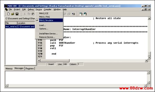
Figure 3. The MAXQ Simulator is accessed from the Device menu.
The MAXQ Simulator supports MAXQ10, MAXQ20, and MAXQ30 devices.
To select the device, click on Device→Options, as illustrated in Figure 4.
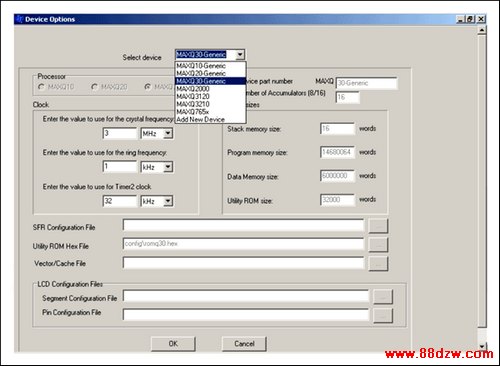
Figure 4. The Options window asks you to choose a MAXQ device.
The drop-down menu in Figure 4 shows the available devices, which consist of specific MAXQ devices (e.g., MAXQ2000) and generic devices (e.g., MAXQ10―Generic for a MAXQ10 architecture). Note that when you choose a specific device like the MAXQ2000, the Processor is selected automatically. If, for example, the MAXQ2000 is selected, the MAXQ20 would be selected automatically as its processor. The user can also change the value for crystal frequency, ring frequency, and Timer2 clock. The other fields in this window are non editable.
For this article, we choose the MAXQ30-Generic for the device.
Step 7: There are two ways to compile the project: Make and Build All. Using the Project menu (see Figure 3), Make will compile only those files that changed since the last successful compile. Build All will always compile all the files.
Tag:控制技术,计算机控制技术,工厂电气控制技术,控制技术
《MAX-IDE Simulator User's G》相关文章
- › MAX-IDE Simulator User's G
- › MAX-IDE入门
- › Automatically Initializing Data Segment Values in MAX-IDE
- 在百度中搜索相关文章:MAX-IDE Simulator User's G
- 在谷歌中搜索相关文章:MAX-IDE Simulator User's G
- 在soso中搜索相关文章:MAX-IDE Simulator User's G
- 在搜狗中搜索相关文章:MAX-IDE Simulator User's G
分类导航
最新更新