


 当前位置:
当前位置:安全系统控制与MAXQ2000-Security Syste
[09-13 17:04:28] 来源:http://www.88dzw.com 控制技术 阅读:8633次
文章摘要:Interfacing to the 4 x 4 KeypadKeypads are used in alarm control systems for secure PIN entry, to arm/disarm the system, and to change configurations. The keypad used in this example application consists of 16 switches, organized in a 4 x 4 grid. The switches are tied together in a row and column ma
安全系统控制与MAXQ2000-Security Syste,标签:计算机控制技术,工厂电气控制技术,http://www.88dzw.comInterfacing to the 4 x 4 Keypad
Keypads are used in alarm control systems for secure PIN entry, to arm/disarm the system, and to change configurations. The keypad used in this example application consists of 16 switches, organized in a 4 x 4 grid. The switches are tied together in a row and column matrix (Figure 2) so that depressing a keypad switch connects one row line to one column line. For example, depressing the "3" key connects row 1 and column 3 together.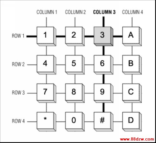
Figure 2. The keypad switches form a grid of four rows and four columns.
The keypad provides eight interface pins, one pin for each row and column of the keypad matrix. The keypad and the MAXQ2000 EV kit are connected as shown.
| Pin | Connect | Port Pin | JU2 Pin |
| 1 | Row 1 | P6.0 | 54 |
| 2 | Row 2 | P6.1 | 52 |
| 3 | Row 3 | P6.2 | 50 |
| 4 | Row 4 | P6.3 | 48 |
| 5 | Col 1 | P6.4 | 46 |
| 6 | Col 2 | P6.5 | 44 |
| 7 | Col 3 | P7.0 | 42 |
| 8 | Col 4 | P7.1 | 40 |
For this application, the EV kit board should be configured as follows.
- DIP switches.
- The following switches must be OFF: All SW1 switches, SW3.1, SW3.7, SW3.8, SW6.1, SW6.4, SW6.5, SW6.6, SW6.7, and SW6.8.
- All other DIP switches can be in any state.
- Jumpers
- The following jumpers must be OPEN: JU5, JU6, JU8, and JU9.
- The following jumpers must be CLOSED: JU1, JU2, JU3 and JU11.
- All other jumpers can be in any state.
Scanning by Columns
The row and column arrangement of the keypad makes it easy to read the state of four switches at any one time, on either a row or column basis. To read four switches in one column, first the line for that column must be pulled low, and all other columns tri-stated (Figure 3). Next, a weak pullup must be set on each row line. Finally, the four row lines are connected to port pin inputs. The input from a row will be low when the switch on that row is depressed, and high otherwise.Similarly, the state of four switches in a row can be read by pulling that row line low and setting inputs and weak pullups on all four columns. The rows and columns are interchangeable.
In our setup, the four row lines (keypad pins 1 through 4) are all connected to the same input port (P6[3:0]), which makes it easier to read them simultaneously. For this reason, the example application scans one column of switches at a time. There are four setup states for the eight port-pin lines connected to the keypad, each of which allows four of the switches to be read. All input lines read low when the switch being read is closed, and high when the switch is open.
上一页 [1] [2] [3] [4] [5] [6] 下一页
Tag:控制技术,计算机控制技术,工厂电气控制技术,控制技术
- 上一篇:利用MAXQ3210进行环境监视
《安全系统控制与MAXQ2000-Security Syste》相关文章
- › 安全系统控制与MAXQ2000-Security Syste
- › FPGA单芯片四核二乘二取二的安全系统
- 在百度中搜索相关文章:安全系统控制与MAXQ2000-Security Syste
- 在谷歌中搜索相关文章:安全系统控制与MAXQ2000-Security Syste
- 在soso中搜索相关文章:安全系统控制与MAXQ2000-Security Syste
- 在搜狗中搜索相关文章:安全系统控制与MAXQ2000-Security Syste
分类导航
最新更新