


 当前位置:
当前位置:热电冷却器控制-Thermoelectric Cooler
[09-13 17:04:53] 来源:http://www.88dzw.com 控制技术 阅读:8969次
文章摘要:Figure 2.The differential network, formed by C1, R1 and R2 in Figure 2, adds another zero to cancel the second 1Hz pole in the TEC module. This provides extra phase margin to close the loop at a higher frequency. This is shown graphically in Figure 1 by the dashed lines. While the fast response asso
热电冷却器控制-Thermoelectric Cooler,标签:计算机控制技术,工厂电气控制技术,http://www.88dzw.com
Figure 2.
The differential network, formed by C1, R1 and R2 in Figure 2, adds another zero to cancel the second 1Hz pole in the TEC module. This provides extra phase margin to close the loop at a higher frequency. This is shown graphically in Figure 1 by the dashed lines. While the fast response associated with high loop bandwidth is not needed, the high DC gain and small caps are. The compensator uses C3 to rolloff the gain at 30Hz to reduce noise injection into the loop. In TEC applications this circuit allows the loop to crossover at 2Hz and provides good phase margin over a wide range.
As a compensation example for a 2Hz crossover we refer to the TEC Thermal Loop in Figure 3. Selecting R3 as high as possible allows the smallest integrator capacitor C2. Because we must insert a zero at 70mHz we use the relation
with Fz1 = 70mHz and selecting R3 = 243K it follows that C2 = 9.36uF. We select 10uF. Now we select R1 = 510K. This allows maximum gain in the front-end amplifier (U2) to reduce the reflected integrator (U1) errors.
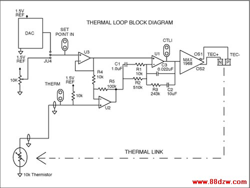
Figure 3.
Now we must insert a zero to cancel the second pole of the TEC at 1Hz. Because we desire good phase margin we insert the zero at the desired crossover frequency divided by at least 5, or 0.4Hz. This gives a better phase margin at the crossover frequency. We then terminate the zero by at least 5 times the crossover frequency, or 10Hz, using R1. This limits the gain of the integrator section after the loop has crossed over.
Because
and with Fz2 = 0.4Hz and R2 = 510K it follows that C1 = 0.78uF. We select 1uF. To find R1 we use the relation
and with F3 = 10Hz and C1 = 1uF we find that R1 = 15.9K. We use 10K to provide better phase margin.
We then must set the roll-off frequency at 30Hz. With R3 = 243k and Fc = 30Hz and
 ,
,we find that C3 = 22nF.
Now that the TEC response has been optimized, the system gain must be adjusted for a cross over at 2 Hz. Graphically we can see from Figure 1 that at 2 Hz the uncompensated transfer function (Solid line, Figure 1) has -30 dB gain. If we desire a 2 Hz unity gain cross over we must provide +30 dB gain at 2 Hz. Because the U1 and its components have gain at 2 Hz, we must subtract this gain from the needed system gain to find the front-end gain. At 2 Hz R3 and C1 define the gain for U1. The reactive impedance of C1, can be found using
Tag:控制技术,计算机控制技术,工厂电气控制技术,控制技术
- 上一篇:单相配电变压器的应用
《热电冷却器控制-Thermoelectric Cooler》相关文章
- › 热电冷却器控制-Thermoelectric Cooler
- 在百度中搜索相关文章:热电冷却器控制-Thermoelectric Cooler
- 在谷歌中搜索相关文章:热电冷却器控制-Thermoelectric Cooler
- 在soso中搜索相关文章:热电冷却器控制-Thermoelectric Cooler
- 在搜狗中搜索相关文章:热电冷却器控制-Thermoelectric Cooler
分类导航
最新更新