


 当前位置:
当前位置:Methods for Calibrating Gain E
[11-20 17:32:04] 来源:http://www.88dzw.com 模拟电子技术 阅读:8480次
文章摘要:Figure 3. A digitally calibrated DAC system.Figure 3 shows an ideal DAC characteristic and an uncalibrated characteristic where the gain error is +10%. By modifying the DAC code, the +10% gain error can be calibrated out. However, this approach introduces a problem that is easily seen by looking at
Methods for Calibrating Gain E,标签:模拟电子技术基础,模拟电子电路,http://www.88dzw.com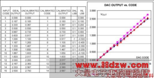
Figure 3. A digitally calibrated DAC system.
Figure 3 shows an ideal DAC characteristic and an uncalibrated characteristic where the gain error is +10%. By modifying the DAC code, the +10% gain error can be calibrated out. However, this approach introduces a problem that is easily seen by looking at calibrated codes and the differential nonlinearity. Initially, the DAC code increases as normal. However, there is a constant positive DNL. The INL increases until 0.5 LSB INL where the calibrated code does not increase from input code 5 to 6. Taking this further, it can be shown that whatever the calibration required, INL will build up to 0.5 LSB before being corrected back 1 LSB. DNL will at some points be + or - 1 LSB. The only way around this is to increase the DAC's resolution.
Digitally calibrating gain error in this way is quite valid and, in fact, Maxim uses this technique in several devices including the MAX5774. The MAX5774 is a 32-channel, 16-bit DAC and a complex device. This part family contains a multiplier and an adder so both gain and offset errors can be calibrated out.
There is a major advantage of calibration with this digital method: calibration can easily be done using ATE. Some, however, view this as a disadvantage, since it does require the use of ATE. Construction and programming of a lookup table or calibration coefficients manually can be done, but it is time consuming and of little value in a practical production situation.
Adjusting the Voltage Reference to Calibrate the Gain Error
Another way to calibrate out gain error is to adjust the voltage reference. This method is particularly suited for systems requiring high accuracy but not necessarily high resolution.
The key to this approach is to use a trimmable reference like the MAX6143. This reference has an initial untrimmed accuracy of 0.04% and a temperature coefficient of 3ppm over -40°C to +125°C. Other trimmable references are shown in Table 1 below.
The MAX6143 can be adjusted by simply adding a potentiometer between output, ground, and the trim pin (Figure 4).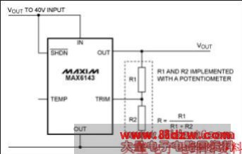
Figure 4. Typical operating schematic for the MAX6143.
The MAX6143's output voltage can be trimmed according to the following equation:

Where:
- VOUT is the output voltage.
- VNOM is the nominal output voltage.
- R is the potentiometer ratio, R = R1/(R1+R2).
- k is typically 0.06 (6%) for the MAX6143.
Therefore, at the extremes, R = 0 and R = 1. With R = 0, VOUT = VNOM × 1.06. With R = 1, VOUT = VNOM × 0.946.
Implementing Voltage-Reference Trimming
- 上一篇:运算放大器的噪声
《Methods for Calibrating Gain E》相关文章
- › Methods for Calibrating Gain E
- 在百度中搜索相关文章:Methods for Calibrating Gain E
- 在谷歌中搜索相关文章:Methods for Calibrating Gain E
- 在soso中搜索相关文章:Methods for Calibrating Gain E
- 在搜狗中搜索相关文章:Methods for Calibrating Gain E