


 当前位置:
当前位置:Methods for Calibrating Gain E
[11-20 17:32:04] 来源:http://www.88dzw.com 模拟电子技术 阅读:8480次
文章摘要:Methods for Calibrating Gain Error in Data-Converter SystemsAbstract: All data-converter systems require a voltage reference. High-accuracy systems suffer from many sources of error, with system gain error among the most important. This gain error can be calibrated out with several methods. Digital
Methods for Calibrating Gain E,标签:模拟电子技术基础,模拟电子电路,http://www.88dzw.comMethods for Calibrating Gain Error in Data-Converter Systems
Abstract: All data-converter systems require a voltage reference. High-accuracy systems suffer from many sources of error, with system gain error among the most important. This gain error can be calibrated out with several methods. Digital calibration is common, but introduces errors, which can be compensated with an increase in resolution. Calibration can also be done by trimming the voltage reference, a method that does not introduce errors. This applications note describes how a voltage reference can be trimmed using a digital potentiometer.
The Problem of Gain Error
A commonly asked training question is: at what resolution would you expect to use a discrete voltage reference in a data-converter system? Novice answers usually suggest the 10-/12-bit region. Well perhaps, but this is a trick question. The real answer is that resolution and accuracy are separate entities. The correct, best answer is understandable in general terms: a high-resolution data converter will be more accurate than a low-resolution data converter. But, there is still more to the answer. A system using low resolution can be made highly accurate with an accurate reference, calibration, or both.
Many factors affect the accuracy of a data-converter system, with gain error among the most important. Gain error is defined as the deviation from ideal at maximum code, ignoring offset error as shown below in Figure 1 for a DAC. ADCs are defined in the same way.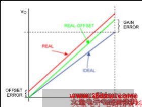
Figure 1. Gain and offset errors.
Digitally Calibrating Gain Error
Gain error is caused by nonideal gain in the analog signal chain and errors in the voltage reference. The error can be calibrated out digitally. However, the digital approach requires the system to use a higher-resolution converter, which can easily increase cost.
This digital method is demonstrated below using an exaggerated example. The system is modeled using an ideal DAC and a nonideal analog output amplifier (Figure 2). To make things simple, assume that the DAC has only 4-bit resolution.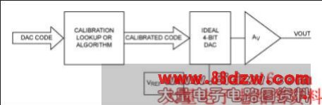
Figure 2. System to demonstrate digital gain calibration.
First consider the ideal situation where the system's gain error is zero, AV = 1. As the DAC input code increases, the output voltage increases accordingly to 2.5V (VREF = 2.5V). Now we make the situation more real, although exaggerated. The gain, AV, is 1.1 (gain error = 10%). The output voltage increases as before, but at code 15. Now VOUT = 2.75V. We can calibrate the system digitally by modifying the DAC code with a lookup table, or by implementing an algorithm in the digital domain. To correct a gain of 1.1 back to an overall gain of 1.0, multiply the code by 1/1.1 = 0.909 (Figure 3). The characteristics of the ideal uncalibrated and calibrated real systems are also plotted.
- 上一篇:运算放大器的噪声
《Methods for Calibrating Gain E》相关文章
- › Methods for Calibrating Gain E
- 在百度中搜索相关文章:Methods for Calibrating Gain E
- 在谷歌中搜索相关文章:Methods for Calibrating Gain E
- 在soso中搜索相关文章:Methods for Calibrating Gain E
- 在搜狗中搜索相关文章:Methods for Calibrating Gain E