


 当前位置:
当前位置:控制DS1804采用8051兼容微控制器-Controlli
[09-13 17:04:14] 来源:http://www.88dzw.com 控制技术 阅读:8106次
文章摘要:Abstract: The DS1804 is a digital potentiometer with EEPROM memory with an interface designed primarily to be interfaced to a pushbutton (human interface). With careful consideration as to the functionality of these pushbutton controls, the DS1804 can also be interfaced directly to a microcontroller
控制DS1804采用8051兼容微控制器-Controlli,标签:计算机控制技术,工厂电气控制技术,http://www.88dzw.comAbstract: The DS1804 is a digital potentiometer with EEPROM memory with an interface designed primarily to be interfaced to a pushbutton (human interface). With careful consideration as to the functionality of these pushbutton controls, the DS1804 can also be interfaced directly to a microcontroller via the pushbutton pins. This application note describes how to do this with an example given using an 8051-type processor. Source code in assembly language is also given to simplify the design task for engineers trying to use the DS1804 in this type of application. Topics covered include:
- How to change the potentiometer setting without updating the EEPROM.
- How to change the potentiometer setting with changing the EEPROM.
- How to write the current potentiometer setting into EEPROM memory.
Introduction
The DS1804 Nonvolatile (NV) Trimmer Potentiometer is ideal for use in any system that requires a biasing voltage, current, or resistance with or without manual adjustments. Its increment/decrement interface allows either the use of minimal external hardware for manual adjustments or a microcontoller for autonomous operation. The wiper can be adjusted to one of 100 positions, and any value can be stored in the part's NV register to select the wiper value at power-up. The part also offers several small packaging options, including 8-pin DIP, SOIC, µSOP, and flip-chip packages.This application note provides a simple hardware and software set-up for controlling the DS1804 with a Dallas Semiconductor DS87C520 (8051) Microcontroller.
Hardware Setup for Microcontoller Communication with a DS1804
One of the primary benefits of using a DS1804 is the simplicity of the hardware and software control interface. Only three connections are required between the potentiometer and the microcontroller: chip select, up/down select, and increment, which are on pins P1.6, P1.5, and P1.4 of the microcontroller in Figure 1, respectively. Two additional components for supporting the 8051 program are shown on the schematic. The first is a EconOscillator chip that provides a 22.22 MHz clock for the 8051; an LED attached to P1.0 is the second. Functioning as a status indicator in the program, the LED is toggled intermittently to show that the program is still executing.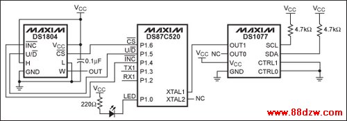
Figure 1. Schematic showing the DS87C520 and DS1804 connections.
The DS1077 can be replaced with a 22.118 MHz crystal. Instructions for operating the DS87C520 with a crystal clock source are available in Dallas Semiconductor's High Speed Microcontroller User's Manual. It should be noted that the DS87C520 is capable of operating with up to a 33 MHz clock; however, the delays used in the software depend upon the clock frequency. Operating the DS87C520 at a higher clock rate can potentially cause timing faults with the DS1804, while operating at a lower frequency should have no ill effects.
Using the CS, INC, and UD Signals to Control the DS1804
Operation of the DS1804 is simple, but a couple of nuances need to be understood for reliable operation. First, the device powers up over the course of 50ms. Attempts to signal information to the part before that period of time elapses will not be successful. The part also requires 500µs to adjust the value of the wiper to the value stored in the non-volatile register during power-up.
Tag:控制技术,计算机控制技术,工厂电气控制技术,控制技术
《控制DS1804采用8051兼容微控制器-Controlli》相关文章
- › 控制DS1804采用8051兼容微控制器-Controlli
- 在百度中搜索相关文章:控制DS1804采用8051兼容微控制器-Controlli
- 在谷歌中搜索相关文章:控制DS1804采用8051兼容微控制器-Controlli
- 在soso中搜索相关文章:控制DS1804采用8051兼容微控制器-Controlli
- 在搜狗中搜索相关文章:控制DS1804采用8051兼容微控制器-Controlli
分类导航
最新更新