


 当前位置:
当前位置:Using the DS87C530/DS5250 Real
[09-13 17:03:26] 来源:http://www.88dzw.com 控制技术 阅读:8357次
文章摘要:Noise and Crystal Layout GuidelinesThe crystal inputs of the RTC (RTCX1, RTCX2) have a very high impedance. Unfortunately, this can cause the leads to the crystal to function as antennae, coupling high frequency signals into the RTC circuitry from the rest of the system. This can lead to a distortio
Using the DS87C530/DS5250 Real,标签:计算机控制技术,工厂电气控制技术,http://www.88dzw.comNoise and Crystal Layout Guidelines
The crystal inputs of the RTC (RTCX1, RTCX2) have a very high impedance. Unfortunately, this can cause the leads to the crystal to function as antennae, coupling high frequency signals into the RTC circuitry from the rest of the system. This can lead to a distortion of the crystal oscillator signal, resulting in extra or missed clock edges. In most situations high frequency noise will present the greatest problem, causing the clock to run fast.The following procedure can be used to determine if noise is the cause of the inaccuracy of a RTC:
- Power the system up and synchronize the RTC to a known, accurate clock
- Remove VCC to the device (but maintain VBAT)
- Wait for a long period of time (24 hours)
- Apply VCC, read the RTC, and compare to the known, accurate clock
- Resynchronize the RTC to the known, accurate clock
- Keep system powered up and wait for the same period of time in step 3
- Read RTC and compare to the known, accurate clock.
Because the crystal pins are highly susceptible to coupling noise, care must be taken when locating the external crystal on the PCB and when routing traces. The following guidelines are presented to reduce the effect of external noise on the RTC.
- Place the crystal as close as possible to the RTCX1 and RTCX2 pins. Short traces reduce stray capacitance and noise coupling.
- Keep the use small crystal bond pads and short traces to the RTCX1 and RTCX2 pins. Larger pads and longer traces are more likely to couple noise from adjacent circuits.
- Place a ground guard ring around the crystal. This helps isolate the crystal from adjacent signals
- Avoid routing signals beneath the crystal or RTCX1/RTCX2 traces. This helps isolate the crystal from adjacent signals. It is especially important to keep high frequency signals and devices as far away from the crystal as possible.
- Place a local ground plane directly beneath the ground guard ring. This helps isolate the crystal from signal layers below the crystal.
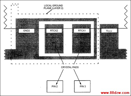
Figure 2. Example crystal placement on PC board.
<-- END: DB HTML -->
上一页 [1] [2] [3] [4] [5] [6] [7] [8] [9] [10]
Tag:控制技术,计算机控制技术,工厂电气控制技术,控制技术
《Using the DS87C530/DS5250 Real》相关文章
- › 利用液晶的MAXQ微控制器-Using an LCD wit
- › Using Timers in the MAXQ Famil
- › Using Analog Temperature Senso
- › Using the DS87C530/DS5250 Real
- 在百度中搜索相关文章:Using the DS87C530/DS5250 Real
- 在谷歌中搜索相关文章:Using the DS87C530/DS5250 Real
- 在soso中搜索相关文章:Using the DS87C530/DS5250 Real
- 在搜狗中搜索相关文章:Using the DS87C530/DS5250 Real
分类导航
最新更新