


 当前位置:
当前位置:Using the DS87C530/DS5250 Real
[09-13 17:03:26] 来源:http://www.88dzw.com 控制技术 阅读:8357次
文章摘要:RTC Software TricksThere are a number of simple tricks that can be used to simplify software associated with RTC operations. The 4-machine cycle delay can be performed using a CJNE A,A,$ instruction. Compared to using 4 NOPs, this is a single instruction, and is 1 byte shorter.The RTC allows sof
Using the DS87C530/DS5250 Real,标签:计算机控制技术,工厂电气控制技术,http://www.88dzw.comRTC Software Tricks
There are a number of simple tricks that can be used to simplify software associated with RTC operations. The 4-machine cycle delay can be performed using a CJNE A,A,$ instruction. Compared to using 4 NOPs, this is a single instruction, and is 1 byte shorter.The RTC allows software to dynamically vary the alarm registers to achieve a wide range of intervals. Often software will want to interrupt regularly on half-increments of time (every 30 seconds, 30 minutes, etc.). This can be easily done using the XRL instruction. For example, if the RTAM register is set to 00h, the instruction XRL RTAM, #1Eh will change the contents to 1Eh. Performing the instruction again will change it back to 00h. Placing this instruction at the start of the RTC interrupt routine will cause the appropriate alarm register to be easily and quickly modified each time the interrupt is called.
Program Example: DATALOGGER
The following program illustrates a generic scheme for operating a remote data logging station. In this example, a DS87C530 is awakened from Stop mode every 30 minutes to read the temperature from a Dallas Semiconductor DS1620 Digital Thermometer and Thermostat. The DS1620 is addressed via serial port 0, using serial mode 0. When the interrupt is called, the DS87C530 will use the ring oscillator to perform a fast resume from Stop and signal the thermostat to begin a temperature conversion. It will then reset the RTC alarm to occur again in 1 second. This will allow time for the conversion and the crystal warm-up period to complete, after which the device will automatically switch back to the crystal as the clock source. The DS87C530 will read the temperature and transmit it, along with the hour and minute, back to a host system connected to serial port 1. It will then return to Stop mode to await the next alarm. Figure 1 shows a partial schematic for interfacing the DS87C530 and DS1620. If the DS1620 is to be separated from the microcontroller by a long distance, filtering may be necessary on the clock and data lines to reduce noise.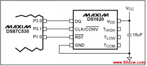
Figure 1. DS1620 interface example.
;Program DATALOGR.ASM
;
;This program demonstrates how to use the RTC to periodically service an
;external device. The device halts in Stop mode until awoken by an RTC interrupt
;every half hour. It then reads the temperature from a DS1620 Digital
;Thermostat and transmits it, with a time stamp, to the host via serial port 1.

;Register equate table
SP equ 81h ;Stack Pointer
PCON equ 87h ;Power Control Register
TCON equ 88h ;Timer Control Register
TMOD equ 89h ;Timer Mode Register
TH1 equ 8Dh ;Timer 1 MSB
CKCON equ 8Eh ;Clock Control Register
P1 equ 90h ;Port 1
EXIF equ 91h ;External Interrupt Flag Register
SCON0 equ 98h ;Serial Port 0 Control Register
SBUF0 equ 99h ;Serial Port 0 Data Buffer
P3 equ 0B0h ;Port 3
SCON1 equ 0C0h ;Serial Port 1 Control Register
SBUF1 equ 0C1h ;Serial Port 1 Data Buffer
TA equ 0C7h ;Timed Access Register
WDCON equ 0D8h ;Watchdog Control Register
ACC equ 0E0h ;Accumulator
RTASS equ 0F2h ;Real-time Alarm Subsecond Register
RTAS equ 0F3h ;Real-time Alarm Second Register
RTAM equ 0F4h ;Real-time Alarm Minute Register
RTCC equ 0F9h ;Real-time Clock Control
RTCM equ 0FCh ;Real-time Clock Minute Register
RTCH equ 0FDh ;Real-time Clock Hour Register

;Bit equate table
RI0 equ 098h
TI0 equ 099h
REN0 equ 09Ch
EA equ 0AFh
TI1 equ 0C1h
ERTCI equ 0Edh

DS1620_RST equ 090h ;DS1620 reset pin is tied to DS87C530 P1.0.
WR_CONFIG equ 0Ch ;DS1620 Write Configuration command.
RD_TEMP equ 0AAh ;DS1620 Read Temperature command.
START_CONV equ 0EEh ;DS1620 Start Conversion command.

cseg at 0 ;Reset vector.
LJMP START
cseg at 6Bh ;Real-time clock Interrupt vector.
LJMP RTC_INT
;
cseg at 100H ;Beginning of code segment.

START: MOV SP, #40h ;Initialize Stack pointer.
MOV EXIF, #0Ah ;Enable ring oscillator restart from Stop mode.
MOV P3, #03h ;Set P3.1 & P3.0 high to use serial port 0.
MOV SCON0, #20h ;Set serial port mode 0, 4 tclk.

MOV P1, #0Ch ;Set P1.2 & P1.3 high to use serial port 1.
;Clear P1.0 to reset DS1620.
MOV SCON1, #40h ;Set serial port mode 1.
MOV TMOD, #20h ;Configure timer 1 for 9600 baud
MOV TH1, #0FDh ; at 11.0592MHz.
MOV TCON, #40h ;Start timer.
;Configure the DS1620
SETB DS1620_RST ;Remove DS1620 reset to start operation.
MOV A, #WR_CONFIG ;Send command to address configuration byte.
CALL OUT_1620
MOV A, #03h ;Set Configuration byte = CPU & 1-Shot Mode.
CALL OUT_1620
CLR DS1620_RST ;Assert DS1620 to end operation.

;Set up the RTC
MOV RTAM, #00h ;Clear all alarm registers. Alarm will ring
MOV RTAS, #00h ; on the next hour to start temperature
MOV RTASS, #00h ; conversion.
MOV RTCC, #081h ;Set alarms so we get a reading at start.
SETB ERTCI ;Enable RTC interrupt.
SETB EA ;Global interrupt enable.

MAIN: ORL PCON, #02h ;Set STOP bit to enter Stop mode.
JMP MAIN ;End of main program loop. Program will return
; here after RTC interrupt is complete.

;***************************************************************************
;RTC_INT - This ISR reads the temp from the DS1620 and outputs the data to
; serial port 1. The routine starts the conversion, and waits for 1
; second to allow conversion to complete and crystal to stabilize.
; When the conversion is complete, the device will read the temperature
; and send the hour, minute and temperature to the host. The RTAM
; register will be modified to alarm again in 30 minutes.
;***************************************************************************
RTC_INT: MOV RTCC, #081h ;Clear RTCI flag and second compare enable
; bit to generate another alarm in 1 second.
PUSH ACC ;Save accumulator.

SETB DS1620_RST ;Remove DS1620 reset to start operation.
MOV A, #START_CONV ;Initiate first temp conversion.
CALL OUT_1620
CLR DS1620_RST ;Assert DS1620 to end operation.
ORL RTCC, #08h ;Enable RTC read process, and delay 4 machine
CJNE A, ACC, $ ; cycles for time registers to stabilize.
MOV R7, RTCM ;Save minute and hour so we can transmit
MOV R6, RTCH ; them as soon as crystal has stabilized.
ANL RTCC, #0F7h ;Reenable time register updates.

WAIT: MOV A, RTCC ;Wait for RTC interrupt flag to be set,
JNB ACC.1, WAIT ; indicating that conversion is done. The
; one second delay will be sufficient for the
; crystal to stabilize, so switch to it now.
XRL RTAM, #1Eh ;Change alarm to ring on next half hour.
MOV RTCC, #0E1h ;Clear RTCI flag, and set compare bits
; so next alarm will be generated in 30 min.
MOV A, #'!' ;Transmit start character.
CALL OUT_HOST

MOV A, R6 ;Transmit the hour.
CALL OUT_HOST
MOV A, R7 ;Transmit the minute.
CALL OUT_HOST

SETB DS1620_RST ;Remove DS1620 reset to start operation.
MOV A, #RD_TEMP ;Conversion is done. Send command to read temp.
CALL OUT_1620
CALL IN_1620 ;Read LSB of temperature and send it to host.
CALL IN_1620 ;Read MSB of temperature and send it to host.
CLR DS1620_RST ;Assert DS1620 to end operation.

POP ACC ;Restore accumulator and go back to sleep.
RETI

;************************************************************************
;OUT_HOST - This routine sends data to the host system via serial port 1.
;************************************************************************
OUT_HOST: MOV SBUF1, A ;Move out byte.
JNB TI1, $ ;Wait until data has been transmitted.
CLR TI1 ;Clear TI1.
RET

;************************************************************************
;OUT_1620 - This routine sends data to the DS1620 via serial port 0.
;************************************************************************
OUT_1620: MOV SBUF0, A ;Move out byte.
JNB TI0, $ ;Wait until data has been transmitted.
CLR TI0 ;Clear TI1.
RET

;************************************************************************
;IN_1620 - This routine reads a byte from the DS1620 and echoes it back
; through serial port 1.
;************************************************************************
IN_1620: SETB REN0 ;Enable receiver to clock in data.
JNB RI0, $ ;Wait until data has been received.
CLR REN0 ;Disable receiver to prevent reception.
CLR RI0 ;Clear RI.
MOV A, SBUF0 ;Echo data through serial port 1.
CALL OUT_HOST
RET
上一页 [1] [2] [3] [4] [5] [6] [7] [8] [9] [10] 下一页
Tag:控制技术,计算机控制技术,工厂电气控制技术,控制技术
《Using the DS87C530/DS5250 Real》相关文章
- › 利用液晶的MAXQ微控制器-Using an LCD wit
- › Using Timers in the MAXQ Famil
- › Using Analog Temperature Senso
- › Using the DS87C530/DS5250 Real
- 在百度中搜索相关文章:Using the DS87C530/DS5250 Real
- 在谷歌中搜索相关文章:Using the DS87C530/DS5250 Real
- 在soso中搜索相关文章:Using the DS87C530/DS5250 Real
- 在搜狗中搜索相关文章:Using the DS87C530/DS5250 Real
分类导航
最新更新