


 当前位置:
当前位置:热插拔控制器改善电力供应测序-Hot-Swap Contro
[09-13 17:03:57] 来源:http://www.88dzw.com 控制技术 阅读:8121次
文章摘要:Abstract: Hot-swap controller ICs implement desired sequence for power-supply voltages. For many systems, the power-supply voltages must be applied in a definite sequence to prevent circuit damage. That task was implemented with discrete circuitry in the past, but modern hot-swap-controller ICs offe
热插拔控制器改善电力供应测序-Hot-Swap Contro,标签:计算机控制技术,工厂电气控制技术,http://www.88dzw.comAbstract: Hot-swap controller ICs implement desired sequence for power-supply voltages.
For many systems, the power-supply voltages must be applied in a definite sequence to prevent circuit damage. That task was implemented with discrete circuitry in the past, but modern hot-swap-controller ICs offer an alternative that simplifies the design and increases the performance of power-supply sequencers.
The circuit of Figure 1 provides power-up sequencing for a variety of hot-swap applications, and can be expanded to control many other supply-voltage combinations. This configuration shows three hot-swap controllers (U1-U3) used to control two positive voltages in the range +9V to +72V (V1+, V2+), and one negative voltage in the range -9V to -100V (V3-).
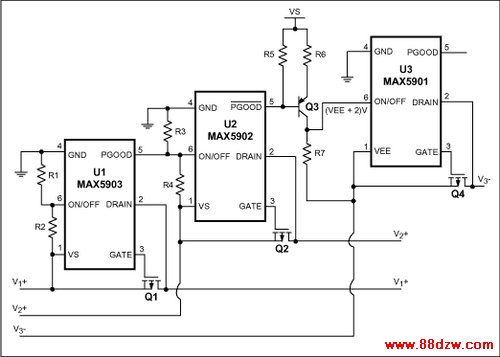
Figure 1. Three hot-swap controllers govern the sequence in which supply voltages appear at the three right-hand terminals.
Hot-swap controller U1 controls the first supply voltage in the sequence to be brought up. Power-up on V1+ will not commence until V1+ is above its preset undervoltage-lockout level (UVLO), and the system temperature is under 125°C. When those conditions are met, U1 initiates the sequence. It slowly enhances the MOSFET Q1 to limit inrush current to the load, thereby reducing load transients.
When the difference between V1+ and DRAIN (pin 2) is less than U1's internal threshold, it asserts PGOOD (pin 5) through a pull-up resistor. PGOOD is used as the power supply to turn on the next controller (U2) in the sequence. This process repeats for each supply voltage in turn, until all supplies are turned on.
If a controller encounters a fault condition such as an input voltage below UVLO, either during the power-up sequence or after full power-up, the hot swap controllers from that point on will turn off. The start-up sequence re-initiates only when the fault is removed.
UVLO levels for the positive supplies are set via the controllers' ON/OFF inputs:

U3 and an n-channel MOSFET control the negative supply voltage. Because its ON/OFF input is referenced to a negative voltage, the /PGOOD\ output from U2 makes a transition from positive to negative sequencing. The level-shifting transistor (Q3) that asserts ON/OFF also enables the setting of UVLO for this negative controller:

Figure 2 shows the power-up sequence for V1+, V2+ and V3- as the circuit board is inserted into a hot socket. Power On represents insertion of the circuit, with the supply voltages V1+, V2+, and V3- up and waiting in the socket.
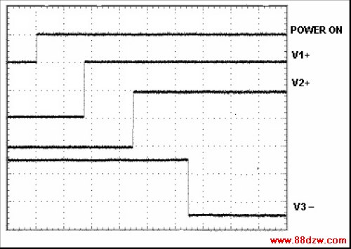
Figure 2. For a circuit board plugged into a hot socket at the moment indicated by POWER ON, these waveforms illustrate the sequence in which supply voltages are admitted to the board.
This former Design Note was published in the October 20, 2003 issue of EE Times magazine.
<-- END: DB HTML -->
《热插拔控制器改善电力供应测序-Hot-Swap Contro》相关文章
- › 热插拔控制器改善电力供应测序-Hot-Swap Contro
- › 热插拔控制器集成电路制造Ajustable断路器-Hot-S
- › 降低热插拔控制电路的电路电流
- › 凌特推出具有板载ADC的四通道I2C热插拔控制器LTC4245
- 在百度中搜索相关文章:热插拔控制器改善电力供应测序-Hot-Swap Contro
- 在谷歌中搜索相关文章:热插拔控制器改善电力供应测序-Hot-Swap Contro
- 在soso中搜索相关文章:热插拔控制器改善电力供应测序-Hot-Swap Contro
- 在搜狗中搜索相关文章:热插拔控制器改善电力供应测序-Hot-Swap Contro