


 当前位置:
当前位置:检测电路保持您的微处理器控制-Supervisory Cir
[09-13 17:05:09] 来源:http://www.88dzw.com 控制技术 阅读:8332次
文章摘要:Figure 7. Multiple ICs provide supervisory protection for a sophisticated mission-critical system.Because the de-facto standard interface between a controller and a motor drive is a ±10V signal, the XMP generates ±15V supply voltages with on-board DC-DC converters to power the output stages. It util
检测电路保持您的微处理器控制-Supervisory Cir,标签:计算机控制技术,工厂电气控制技术,http://www.88dzw.com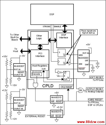
Figure 7. Multiple ICs provide supervisory protection for a sophisticated mission-critical system.
Because the de-facto standard interface between a controller and a motor drive is a ±10V signal, the XMP generates ±15V supply voltages with on-board DC-DC converters to power the output stages. It utilizes these voltages as well as the ±12V, +5V, and +3.3V that are standard with CPCI specifications. For the PCI version of the motion controller, 3.3V is derived from 5V using another DC-DC converter. Because the analog outputs control motor speed (or torque) directly, they reset to zero during a fault condition. The system monitors all supply voltages, and it shuts down the analog outputs if any supply voltage goes out of spec.
Similarly, the hardware employs a watchdog timer (WDT) to guard itself, the motors, and the motor loads against the effect of software problems. The WDT's short timeout (4ms) catches error conditions before damage is done. At boot-up, the WDT must hold off until the host computer and XMP power up and become synchronized. Then, the WDT becomes enabled in such a fashion that the software cannot disable it again without a full reset of the DSP.
The host computer or an external signal can also trigger a hard reset, one that causes a complete reboot, placing the board in the same state as that following an initial power-up. The WDT triggers soft resets only, which reset the analog outputs and cause the FPGAs to reset their I/O without reloading their configurations. The soft reset condition is latched until the host decides what to do. All other sources cause hard resets.
One MAX6307 monitors the ±15V supplies; another monitors the ±12V supplies. As described above, the overvoltage inputs serve as undervoltage detectors for the negative supply voltages. The open-drain reset outputs are wire-ORed and gated with a reset generated by the host, which writes a specific value through the PCI interface to a CPLD register. The result is applied to the Manual Reset (/MR\) input of a MAX6315, and an External Reset input is applied to the /MR\ input of another MAX6315. One '6315 (factory set for 4.63V) monitors the 5V supply, and the other (factory set for 2.93V) monitors the 3.3V supply. Their wire-ORed outputs produce hard resets that cause the entire board to return to the power-up state.
A MAX6303 in a µMAX package is used for the watchdog timer. This device uses two external capacitors to set independent timeout periods for the watchdog and reset functions. The watchdog period is multiplied by 1X or 500X according to the state of the WDS digital input. The combination of an external WDT capacitor and the WDS pin provides WDT periods from 100µs to many minutes. The MAX6303 also has an undervoltage detector (not used) that is set with two external resistors.
Driving the MAX6303 WDS pin high and floating its WDI input disables its WDT. Employing this feature and two flags in the DSP circuitry in a CPLD on the XMP disables the MAX6303's WDT after a hard reset. The first flag serves as the WDT STROBE; the second as the WDT /ENABLE\ (low true). The STROBE signal goes through a three-state buffer in the CPLD before being applied to WDI. The ENABLE signal is registered by a flip-flop on the CPLD, and the flip-flop output controls the strobe's three-state buffer.
上一页 [1] [2] [3] [4] [5] [6] [7] [8] 下一页
Tag:控制技术,计算机控制技术,工厂电气控制技术,控制技术
《检测电路保持您的微处理器控制-Supervisory Cir》相关文章
- › 恒流源供电和摘机检测电路图
- › 低功耗窗口温度检测电路图
- › 过零检测电路图
- › 电压输出式角度检测电路图
- › 电压检测电路图
- › 遥控红外检测电路图
- 在百度中搜索相关文章:检测电路保持您的微处理器控制-Supervisory Cir
- 在谷歌中搜索相关文章:检测电路保持您的微处理器控制-Supervisory Cir
- 在soso中搜索相关文章:检测电路保持您的微处理器控制-Supervisory Cir
- 在搜狗中搜索相关文章:检测电路保持您的微处理器控制-Supervisory Cir
分类导航
最新更新